During week 2, the FSAE Electric Racecar team was visited by Karma Automotive. They gave feedback on our current designs, showed their current cars, and gave a presentation about their company.
Additionally, we were able to complete the design of our body. The body will be made out of a combination of wood and fiberglass and weigh less than 25 pounds.
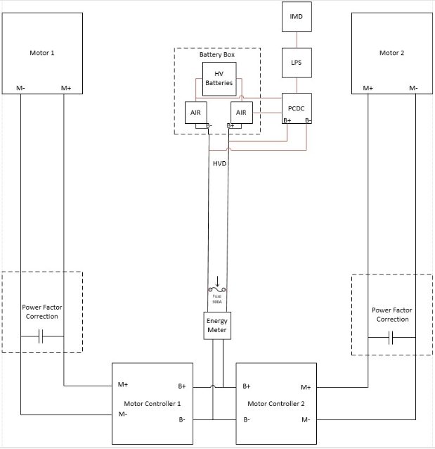
This week, Tyler Ishikawa-Kurokawa will be describing the high voltage system.
The high voltage system controls the flow of power from the batteries to the motors. It consists of the motor controllers, the Motor Controller Isolator, the Power Factor Corrector, the Discharge Board, and the Energy Meter. These components will be placed in a box that will secure them so that the high voltage can not harm people and they will not move.
The motor controllers act as the brain of the high voltage system as they control the rate the motor rotates and how much power is drawn from the batteries. The controllers take input from the low voltage system and vary their output depending on the information that the low voltage system is sending.
To allow the high voltage system and low voltage system to communicate without damaging the low voltage system (the high voltage would fry the low voltage system’s components), the systems need to be electrically isolated from each other. These systems are electrically isolated by the Motor Controller Isolator circuit that uses an optocoupler. The optocoupler works by emitting a light when the low voltage system sends a signal. The light tells the high voltage side to activate the motor controllers.
Another high voltage circuit is the Power Factor Corrector that will reduce the imaginary impedance due to the inductance of the motor and the capacitance of the motor controllers. The goal of reducing the imaginary impedance is to eliminate the reactive power from the magnetic effect of inductors and the electric effects of capacitance. In our case, the imaginary impedance is positive so we need to add a capacitor to get some negative impedance to get a final result of zero imaginary impedance.
The FSAE Energy Meter is a component required for the FSAE competition, and it is required to be located between the connection of the battery box and motor controllers. This allows it to connect to the highest potential and lowest potential of the tractive system. During the competition, the judges will use this meter to get measurements of the energy of our car, but to also check the security of the high voltage system.