Although the exterior has been build minor modifications are still being made to place all component accordingly in the interior of the body. We have also been working on trouble shooting all the components and connecting all together. In working with electric components, specifications need to be read carefully to ensure that the correct voltage and amperage are given to each system. The signal is also a very important part in having this prototype function property. The concept behind having all components being signal by a microcontroller is to that a single touch of a button can dispense both the food and supplement. In previous testing, we were using an Arduino Uno but due to the complexity and the number of signal pins require by all subsystem we will have the final prototype be controlled by an Arduino Mega.
This week we have emphasize in mounting all electrical component for subsystem one, two and four. For subsystem one the stepper motor, and its motor driver were the 2 components needed to be integrated. For subsystem two there are a total of four solenoid valves, four pumps, buck converter, motor drive converter and a 24V to 5V converter. The reason for multiple converters is due to the voltage requirement per component. As mentioned in some of the previous blogs solenoid require 12V while pumps can range from 3V to a max of 6V, relay a require 5Vand lastly the stepper motor requires 24V. Therefore, the main power supply will output 24V, and with the according converter we will drop down the voltage as needed. We are still working on perfecting the prototype with testing. We are having some issue with the dispensing of the correct supplement when pressing the button on the screen but can be address by reviewing and modifying the main code as all components have been tested individually to work properly with single code for testing purposes.
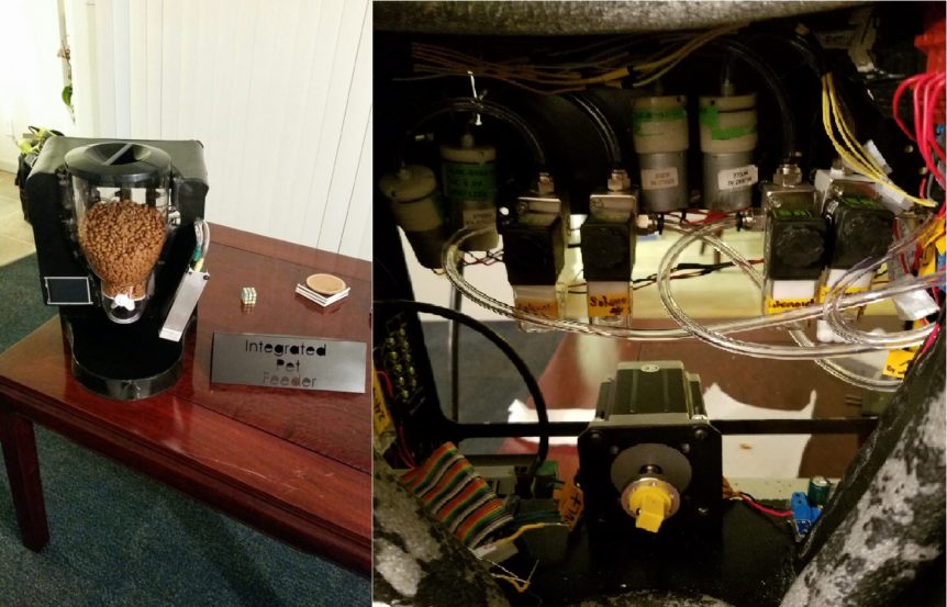
Integrated Pet Feeder for Health and Wellness, Sandy Moreno