For the competition, it is necessary to have a function to control the descent of the CanSat safely and accurately. A design without any descent control is a very risky gamble. We started out with a passive control design with the intent of letting the shape of the CanSat and parachute do the work in slowing the system down, but we decided to move on to an active control setup.
Our active control setup:
- Primarily of carbon fiber walls, nylon fabric, and various attachments
- Nose of heat shield is attached to the probe skeleton via an electromagnet near the nose of the CanSat
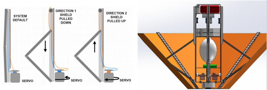
- “Arms” between heat shield and probe give heat shield mobility
- Fishing lines connected to servos (attached to probe) control arms
The descent will consist of 3 phases:
Stage 1: From 700m-325m
- Torque of servo holds heat shield (and all relevant components) in place
- During aero-braking phase, if velocity is too high (above target), servos and fishing lines pull arms down, causing the heat shield to expand outward, thereby increasing the projected area and the associated drag force and decreasing the velocity to approach our target
- Likewise, if velocity is too low (below target), servos and fishing lines pull up on the arms, retracting the heat shield slightly, decreasing the drag force, and increasing the velocity to approach our target
Stage 2: From 325m- 0m
- Heated nichrome wire splits the fishing lines, releasing the heat shield
- Polarity of electromagnetic latch on heat shield is reversed, actively pushing the shield away
- Electromagnetic parachute latch deactivates, releasing the parachute
Stage 3: Parachute Phase
- Passive control
- Parachute size & shape determines CD which controls descent velocity.
— An Nguyen
Telemetry Lead